|
|
|
Kto jest w sklepie?
Sklep przegląda 6043 gości |
|
Kategorie
|
|
Informacje
|
|
Polecamy
|
|
|
 |
|
|
Dla tego produktu nie napisano jeszcze recenzji!
 ;
Schematy są ale można wysilić się i zrobić kolorowy skan i o większej rozdzielczości. Wtedy schematy płytek będą czytelniejsze. Całość super jako wartość merytoryczna. Wszystkie dane potrzebne do podłączenia różnego rodzajów urządzeń takich gramofon, CD itd.
 ;
Szybko, sprawnie i tanio. Serwis godny polecenia. Będę polecał innym
;
Ogólnie jest OK, z wyjątkiem obrazu płyty głównej, który jest miejscami mało czytelny, ale można sobie poradzić.
;
Dokładna dokumentacja, pomogła w szybkiej naprawie telewizora. Dziękuję!
;
jedyne do czego mogę mieć zastrzeżenie to jakość zdjęć zawartych w przesłanej instrukcji serwisowej ponieważ są fatalnej jakości, praktycznie nieczytelne. tak poza tym jestem zadowolony to jest to czego szukałem.
MODEL: WT-42311 / WT-A42
ANODE LEAD REMOVAL
CAUTION: To prevent damage, the following procedure must be used when removing an Anode Lead from the Flyback Transformer.
1) Push the Anode Lead down.
2) While holding the lead down rotate the lead 90º counter clockwise.
3) Carefully remove the Anode Lead from the Flyback Transformer.
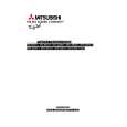
CRT REPLACEMENT
1. Removal of the CRT
Caution! High voltage should be completely discharged prior to CRT removal. Since the CRTs receive high voltage from the Flyback transformer, discharge the CRTs by shorting the open end of the respective high voltage cable to chassis ground.
1. Refer to Cabinet Disassembly and remove the Light Box Assembly. 2. Remove the three Anode Lead Wires from the Flyback transformer and discharge the CRTs. (Use the above procedure) 3. Unplug the three PCB-CRTs. 4. Remove 4 screws "a" retaining the Optical Unit. [Figure 1] 5. Remove 4 screws "b" retaining the Lens of the respective CRT 6. Lift the Optical Unit from the Light Box and set it lens down on a flat surface. 7. Remove 4 screws "c" retaining the CRT. [Figure 2] Note: DO NOT loosen the spring loaded screws. Doing so will break the seal between the C-Element and the # 6 Lens, causing leakage of the CRT Coolant. 8. Remove the Deflection Yoke from the neck of the CRT. [Figure 3]
Figure 1 Page 12
|
|
|
> |
|